Reprinted from Vocal Fold Physiology: Biomechanics, Acoustics and Phonatory Control, Denver Center For Performing Arts (1985), ed Titze and Scherer.
Traduction en français
ABSTRACT
Musicians have always insisted on the importance of getting the proper shapes in a wind-player's air passages. For this reason, the apparent success of the current oscillation theory of reeds and musical air columns without inclusion of the player's windway effects became increasingly mysterious as the subject matured. Since this theory to date has been useful for guiding the construction of fine instruments, confidence in its techniques is sufficient to support a serious attack on the problem of extending it to include the player's windway. Major energy production occurs at frequencies where A[(Zu + Zd)//Zr]≈>l. Here A and Zr are the transconductance and impedance of the reed while Zu and Zd are the input impedances of the air columns looking upstream and downstream from the reed. Nonlinear effects couple these energy sources via heterodyne action, whether or not Zu appears in the accounting. Meaningful extension of theory has been aided by the development of convenient pulse-echo/FFT-measurement techniques for the Z's of both the instrument air column and the player's windway. Most vowel (supraglottal) configurations give rise to Zu peaks in the range of 450 to 1500 Hz that are able to play a significant role for instruments. The fact that these peaks do not coincide with speech formant frequencies has helped to confuse the situation, as has the fact that some players unconsciously exploit windway resonances, while many do not use them at all.
I. INTRODUCTION
This report is intended to provide an introductory account of how the player's own windway interacts with the reed and air column of a musical wind instrument. Our formal understanding of the reed/air-column interaction is extremely good today, to the extent that it is possible not only to describe the acoustical nature of the interaction but also to use it as an effective guide to the instrument maker in his labors to build a good instrument or to improve an already existing one. For this reason, our task is relatively simple: we need only to show how the additional complexities associated with the player's windway modify the mathematical physics of the simpler reed/air-column system and then examine the ways in which the modified system differs in its behavior from the one that has been well studied.
The reader's first reaction to the preceding paragraph may well be a remark such as, "Musicians for hundreds of years have insisted on the importance of the mouth and throat configuration of anyone who is serious about playing a wind instrument. How then can anyone claim to have understood a wind instrument to a useful extent without taking this fact into account? Furthermore, how can he then go on to announce the importance of the player's windway as a new discovery?" It is my hope that the answers to these important questions will themselves clarify the nature of just what it is that has become newly understood.
For many years I have stoutly told my musician friends (and myself, in my incarnation as a serious amateur player) that the role of the player's windway could only be clarified after the other, more easily visible contributors to the musical oscillation were properly elucidated.
As a matter of fact, today the question has inverted itself, taking the form: "How did such a largely influential part of the dynamical system remain incognito during the course of investigations covering many years in which changes of only two or three parts in a thousand of many other acoustical parameters could readily be associated with their dynamical and musical consequences?"
It will perhaps be useful to outline the preceding remarks in the following way before we look at the physics itself.
DOES THE LUNG-THROUGH-MOUTH AIRWAY SIGNIFICANTLY INFLUENCE THE PLAYING OF MUSICAL WIND INSTRUMENTS?
1. MUSICIANS ARE UNANIMOUSLY OF THE OPINION THAT IT DOES.
2. THE MUSICAL ACOUSTICIAN HAS TENDED TO IGNORE THE QUESTION, OR TO SET IT ASIDE AS A RELATIVELY SMALL INFLUENCE.
Item (2) above is a deliberate oversimplification. Measurements and speculations of an acoustical nature have been made over the span of many decades, but for various reasons no clear consensus has developed. The detailed recounting of this branch of history will not contribute appreciably to our present purpose, which is to give a compact description of what is known today, in a form that will (hopefully) be intelligible to a readership whose major concerns are with the biophysics of the player himself rather than with the details of his interaction with a musical wind instrument.
I wish to make clear at this point in my introductory remarks that the present report is intended to be little more than an announcement of some of the recent results obtained in Cleveland. For the sake of brevity, I will therefore run the risk of frustrating my readers and annoying workers elsewhere whose results are not properly acknowledged. I shall, however, mention here by name those of my coworkers past and present who have made particularly large contributions (beyond the limits of any published work of theirs) to the insights reported here; these are Walter Worman, George Jameson, Stephen Thompson, and Peter Hoekje. The present report would not have become possible without their direct collaboration. This is true of George Jameson and Peter Hoekje in particular. Beyond this I will present only those bibliographical details that can directly aid the reader in his comprehension of the present discussion. A formal research report with proper acknowledgement and documentation is being prepared by Hoekje and myself for submission to the Journal of the Acoustical Society of America.
II. FORMULATION OF THE PROBLEM
 Figure
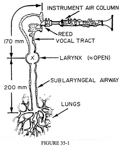
35-1 shows the general nature of the dynamical system with which we are
concerned. The system may be considered as being the concatenation
of four major segments: the sublaryngeal airway (terminated at its lower
end by the player's lungs), the larynx (which in the present case is either
wide open or partially closed in a manner that does not permit it to oscillate),
the vocal tract (which is extensively adjustable via motions of the soft
palate, tongue, jaws, etc.), the reed of the musical instrument (whose operating
point, damping, etc., are controlled by the player's lip position and pressure),
and the musical air column (whose acoustical properties are controlled via
the player's fingers on the various keys and/or tone holes).
Figure
35-1 shows the general nature of the dynamical system with which we are
concerned. The system may be considered as being the concatenation
of four major segments: the sublaryngeal airway (terminated at its lower
end by the player's lungs), the larynx (which in the present case is either
wide open or partially closed in a manner that does not permit it to oscillate),
the vocal tract (which is extensively adjustable via motions of the soft
palate, tongue, jaws, etc.), the reed of the musical instrument (whose operating
point, damping, etc., are controlled by the player's lip position and pressure),
and the musical air column (whose acoustical properties are controlled via
the player's fingers on the various keys and/or tone holes).
In any musical wind instrument, whether woodwind, brass, voice (or even harmonica!), we find three interacting subsystems: an air passage from the wind supply (the player's windway or the organ pipe's foot and the wind chest below it), a flow-control device (the cane or lip reed of the orchestral wind instrument, the singer's larynx, the free reed of the harmonica, or the air reed of the flute player), and finally some sort of resonator and radiating system that ultimately couples with the room into which the sound is to be fed. Setting aside the flute family of instruments, the flow control device is a valve whose degree of closure is determined by the pressure difference across an operating surface.
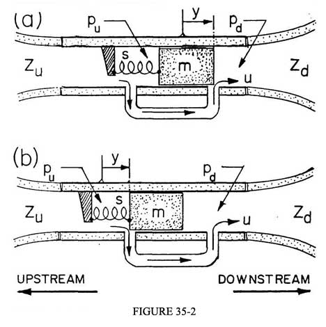
Figure 35-2 shows two versions of the basic pressure-controlled system. One of the controlling pressures is maintained in part by the player's lungs and in part is produced by the acoustic disturbances taking place in the player's windway (PWW). The other pressure acting upon the reed-valve is found within the instrument's mouthpiece as a manifestation of the acoustical activity taking place in the instrument's air column (IAC). In Figure 35-2a the valve action is arranged so that an increase in the downstream pressure pd leads to a greater flow. This arrangement is typical of all the orchestral reed woodwinds and of the organ reed pipes. Figure 35-2b shows, on the other hand, a system in which the valve action is reversed so that an increase of pd decreases the flow u, as is typical in the orchestral brasses.
 We
will find it convenient to define directions in this essentially one-dimensional
waveguide system with the help of the words "upstream" and "downstream," these
being directly related to the direction of the normal flow of air from
the player's lungs out into the room. Thus one of the flow-controlling
pressures acts on the upstream side of the reed, while the other is exerted
on its downstream surface. Terminology based on this convention prevents
ambiguities of the sort that arise if one simply uses the words "up" and "down." For
a clarinetist the airflow runs upward within the player, and then downward
through his instrument. The problem of similar description of what
goes on in a bassoon or tuba defies the imagination!.
We
will find it convenient to define directions in this essentially one-dimensional
waveguide system with the help of the words "upstream" and "downstream," these
being directly related to the direction of the normal flow of air from
the player's lungs out into the room. Thus one of the flow-controlling
pressures acts on the upstream side of the reed, while the other is exerted
on its downstream surface. Terminology based on this convention prevents
ambiguities of the sort that arise if one simply uses the words "up" and "down." For
a clarinetist the airflow runs upward within the player, and then downward
through his instrument. The problem of similar description of what
goes on in a bassoon or tuba defies the imagination!.
We find it useful to characterize the PWW and the IAC via their impedances as seen by the flow controller. We will refer to the impedance looking upstream into the PWW as Zu, while the impedance of the IAC will be denoted by Zd. The reed itself requires two characterizations, since it plays two roles in the complete oscillating system. We define its acoustic impedance Zr in terms of its displacement volume velocity when it moves in response to a driving pressure exerted on either one of its surfaces (see Figure 35-2); the other and perhaps more basic property of the reed is its flow-control characteristic, which is in general a nonlinear function. This flow-control characteristic is most conveniently specified by expressing the flow u as a Taylor expansion in the pressure difference p between the two sides of the reed, as given in Equation 35-1.
u(t) = u0 + A p(t) + B p2(t) + C p3(t) + + + + + (35-1)
Because the reed assembly functions as a spring-mass-damper system, we recognize at once that Zr shows a resonance property that makes it inversely proportional to the factor D(ω) that is set down as Equation 35-2.
 (35-2)
Here ωr is the natural frequency of the reed and gr is its half- power bandwidth. We notice, further, that since the actual flow rate of air through the reed depends on its position (and so only indirectly on the activating pressure), the flow-control coefficients are themselves resonant in their nature. That is, these coefficients may be written as the product of their low-frequency "steady-state" values (A0, B0, C0, . . .) and the factor D(ω) defined above. This fact proves to be very important to our understanding of the way musical instruments are played. We can usefully remark here that A0 is positive for the woodwind valve system of Figure 35-2a and negative for that belonging to the brasses, as in Figure 35-2b.
Let us now write down the pressure and flow relationships on the upstream and downstream sides of the reed, in terms of the impedances Zu, Zd, and Zr. The positive direction of acoustic flow is defined to be the downstream direction of the DC flow from the player's lungs.
u = pd/Zd + (pd - pu)/Zr (35-3a)
-u = pu/Zu + (pu - pd)/Zr (35-3b)
The first term on the right side of each of these equations simply expresses the ordinary relation between pressure at the entryway of a waveguide and the flow that goes into that waveguide. The second term gives a measure of the flow that goes into the region vacated by the reed itself when it moves under the influence of the pressure difference that acts upon its two sides.
Equations 35-3a and 35-3b can be combined in an interesting and useful way: the flow u through the reed aperture can be expressed very simply in terms of the pressure difference p across the reed, as shown in Equation 35-4.
p = u(Zu + Zd)//Zr (35-4)
That is to say, the pressure difference across the reed is proportional to the sum of the upstream and downstream impedances, in parallel with the reed impedance (which tends to be very large compared with the other impedances, so that it has a secondary, though non-trivial, role in the oscillation process). We will use the unadorned symbol Z to represent this combined impedance.
As a preparation for the next step in the discussion, we should recapitulate the nature of the problem whose solution we are trying to outline. When a wind instrument is played, the upstream and downstream impedances (together with the reed's own impedance) are coupled via a flow-controlling valve to the player's lungs, which serve as the primary source of compressed air. The system is kept in oscillation by a feedback loop in which the net acoustical disturbance at the reed (i.e., the pressure difference across it) operates the flow controller, and the resulting flow serves as the excitory stimulus for the upstream and downstream waves.
Equation 35-1 provides us with a formal representation of the pressure-operated flow-control property u(p) of the reed, while Equation 35-4 provides in a very compact form the pressure response property of the entire airway system (PWW + IAC + REED) to a flow stimulus. We should notice that both of these equations relate the flow u, which is the same on both sides of the reed valve, to the pressure difference p across it. In other words, our analysis can be carried out in terms of p and u via the net Z and the "control polynomial" u(p), without our having to worry about the complications of the individual responses of our three subsystems to the flow which they jointly engender via a nonlinear coupling.
From the point of view of mathematical physics we have here an initial explanation of why effects produced by the PWW did not automatically destroy our ability to make meaningful calculations guided by, and checked against, experiments with reeds and various types of IAC—all that was necessary was that the PWW would not produce confusing and distracting effects. We were fortunate, indeed, over a period of many years that such was the case for long enough for us to get a firm grasp of the essential physics.
We turn now in the briefest way to a sketch of how the essential behavior of the system can be understood. Confining our attention for the moment to the case of strictly periodic oscillations in the system, we write the flow u(t) as a Fourier series:
u(t) = Σuncos(nω0t + ψn) (35-5)
Here ω0 represents the frequency of the tone being produced. Term by term this series represents the flow excitation spectrum being applied to the (PWW + IAC + REED) system. Given the (net) impedance Z(ω) of this system, we may write Zn for its magnitude at the frequency nω0 and Φn for its phase. The pressure signal corresponding to u(t) can then be written down.
p(t) = ΣZnuncos(nω0t + ψn + Φn) (35-6)
As a matter of formal mathematics, Equations 35-1, 35-5, and 35-6 can be solved simultaneously to give the pressure spectrum across the reed for a given blowing pressure. While the detailed calculations are very tedious, it proves possible to extract a great deal of useful information about the system. This information, which can be readily checked against the behavior of real systems, depends much more on the overall mathematical structure of the problem than it does on the numerical values of the various parameters. That is, the salient features of the solution can be summarized very simply in a form that depends only on the systematic behavior of nonlinear trigonometric equations. Furthermore, when the complete story is in, we find (surprisingly enough) that the results show almost no sensitivity to the phases of the impedances, or of the reed resonance factor (Equation 35-2)! This is not to say that the phases are irrelevant or that they have random values—merely that the spectrum amplitudes are not sensitive to the phases of the Zn's and the Dn's.
Equations 35-7 and 35-8 will suffice here to indicate the nature of the playing pressure spectrum as measured across the reed. In particular, the fundamental component pl, which is the pressure amplitude of the disturbance at the playing frequency, obeys an equation of the form
Similarly, the higher components have amplitudes that can all be written in the form
I want to point out that in these equations there is no explicit appearance of the phase shifts associated with the flow-control parameters or the impedances. Only the magnitudes are important when the oscillation is of periodic type.
We will postpone discussion of these results until we have sketched out a linear cousin to the analysis, in which we can see what happens to the n'th component of the pressure when looked at by itself, the inescapable nonlinear coupling between spectral components being represented by a flow source Un that is "external" to the component in question.
III. A LINEAR COUSIN TO THE PROBLEM
Suppose that our system is running in a steady oscillation at the frequency ω0, with a part u(t) of the flow being produced through the linear term Ap of the control polynomial, and part of it U(t) being externally imposed by an as-yet-unspecified source having the same periodicity. If we use the Fourier representation, the imposed flow may be written
U(t) = ΣUnejnω0t (35.9)
and the pressure signal across the reed is
p(t) = ΣZn[un + Un]ejnω0t (35.10)
Equation 35-10 may be solved term by term for the flow component amplitudes in terms of the combined impedance Zn and the corresponding transconductance An (evaluated at the frequencies ωn of interest):
un = Anpn = ZnAn[un + Un] (35-11)
whence
un = Un[(ZnAn)/(1 - ZnAn)] (35-12)
Here and in the discussion that follows through Equation 35-13, the symbols An and Zn have their ordinary complex representation; i.e., account is taken of both magnitude and phase. Equation 35-12 has the familiar form that represents the current gain un/Un of a feedback amplifier for which the open-loop gain is ZnAn. It is at once apparent, therefore, that each spectral component of the flow is self-sustaining as an independent oscillator if the real part of the open-loop gain is exactly unity. That is, an energy input provided by the external drive signal Un is not needed to keep the oscillation going.
However, if the open-loop gain ZnAn is less than unity, the amplitude of the flow component un is proportional to Un. Furthermore, the magnitude of un will die away exponentially in time if Un is abruptly shut off, with a decay rate that is proportional to the discrepancy between unity and the magnitude of the real part of ZnAn.
If, on the other hand, the open-loop gain is greater than unity, an exponentially growing oscillation can take place with a growth rate that is once again proportional to the difference between unity and the magnitude of the real part of the open-loop gain. Under these conditions the feedback system is able (for the component in question) to generate more energy than it can dissipate, without need for an additional input via Un.
So far as our present (oversimplified) model is concerned, we may summarize by saying that the oscillation of each spectral component is independent of all the others, and that it is inherently unstable. We are of course very much accustomed to this sort of instability, which is shared by all ordinary oscillators, and it is quite customary to recall the presence of some amplitude-dependent (nonlinear) additional damping which comes into play to stabilize the amplitude of a real oscillator.
In the multicomponent musical oscillator there are, to be sure, several amplitude-dependent sources of damping beyond that implied by Zu, Zd, and Zr (turbulent damping, for example). There is, however, another way in which energy can be transferred in and out of each spectral component, a way that not only assures the stability of each component amplitude under much-less-stringent requirements on the open-loop gain, but also guarantees that the various amplitudes have a well-defined relationship to one another. This is of course an absolute requirement for a musical sound source whose tone color needs to be defined for each condition of playing chosen by its user. The fundamentally nonlinear nature of the control polynomial defined in Equation 35-1 shows (in simplest terms) that whatever pressure signal components pn might be generated via the operations of the linear term in this polynomial, they will immediately breed contributions to the entire collection of flow components at all other harmonic frequencies according to the heterodyne (intermodulation) arithmetic that may be generalized for arbitrary exponents from the trigonometric relation
(McosP) (NcosQ) = (MN/2)[cos(P+Q) + cos(P-Q)] (35-13)
That is, the "externally imposed" flow components Un that were introduced in Equation 35-9 may now be understood to represent in a very simple way (computationally useless but heuristically helpful) the transfer of energy from each modal oscillator to its brothers. It is no longer required that each component be precisely self-sustaining when looked at by itself; all that is required is that as a group the spectral components can jointly produce enough energy to supply their total energy expenditure to the outside world.
Our quasi-linear model provides us one more insight into the nature of the real-world nonlinear system: every spectral component is connected directly or indirectly to every other one, so that its phase is the resultant of many influences. The nature of the oscillation is such that there are many ways in which the actual phase of a given component can be reconciled with those of its conferers. Proper analysis shows that, as a result, the spectral amplitudes are determined almost exclusively by the magnitudes of the relevant Z and A, B, C parameters and not by their phase angles (Thompson 1978).
The discussion so far in this section has shown that energy production is favored at maxima of the A(ω)Z(ω) product. In the woodwinds, A is very nearly A0 over much of the spectral range because the reed's own natural frequency ωr is relatively high (e.g., 2000-3000 Hz for a clarinet). This being so, energy production is favored at the impedance maxima of the PWW-IAC-REED system. This says (if for a moment we ignore Zu and Zr) that oscillation is favored at the normal-mode frequencies of the IAC taken with its reed end closed, as has been recognized for at least 200 years ("the clarinet plays as a stopped pipe").
Another implication of our discussion is that the overall energy production is largest if the impedance maxima are harmonically related to one another. This assures that each of the heterodyne frequency components generated from the harmonics of the played note finds itself matching one of the energy-producing impedance maxima and thus transferring energy to a productive place in the regenerative scheme. Let us put this in more obviously music-related words of the sort used prior to the explicit inclusion of PWW effects: a musical instrument whose impedance maxima (as modified by the parallel but large Zr) are harmonically related is one that starts its tones well, produces a clear sound, provides controllable dynamics and stable pitches, and is otherwise a most attractive instrument in the hands of the player and in the ears of the listener. I have given a very extensive discussion of these matters in chapters 20 through 22 of my book (Benade 1976). Conscious recognition of the usefulness of accurate harmonic "alignments" of the air column resonances led (beginning around 1964) to a continuing evolution of laboratory and workshop techniques for the measurement and correction of the positions of the resonances belonging to essentially all the notes of an instrument's scale. The behavior of instruments adjusted by means of these techniques has been much admired by well-known musicians, and the techniques themselves are beginning to have a significant effect on the making of (at least artist-grade) instruments of all sorts today.
We had temporarily set aside the possibility that the ZA product could become large near the reed frequency ωr, so that the harmonic for which nω0 ≈ ωr might contribute to the net energy production even though Z itself might not be large. While the book contains numerous qualitative remarks concerning the musical usefulness of this possibility in woodwinds, the detailed physics of it was not elucidated till later (Thompson 1979). For present purposes it will suffice to say that all really skilled woodwind players exploit the possibility of an extra energy source at ωr by setting the reed frequency at some (any!) harmonic of the playing frequency in order to further stabilize and purify their sound production via the inclusion of an extra, accurately aligned participant in the "regime of oscillation." For brass instruments, the player must pay attention to ωr, since the note he wishes to play is selected directly by arranging the lip-reed natural frequency to lie just below the fundamental of the desired tone. Further discussion of the curious dynamics of the brass instrument, with its reversed-sign value for the reed transconductance A(ω), would take us too far from the goals of this report. It will suffice for us to notice that the adjustability of the reed resonance frequency is a musically important resource for the woodwind player and an unavoidable necessity for the brass player. In both cases we find that a physiological adjustment is used as an adjunct to the mechanical controls provided by the player's hands on the keys, valves, and slides of his instrument.
We close this part of our thumbnail sketch of the (inherently nonlinear and therefore very stable) sound production mechanism of the orchestral wind instrument by pointing out once more that our understanding of it reached a highly developed state without any account being taken of the possibility that the player's windway could itself play a significant role. Our present analysis has shown that Zu enters the dynamical equations in a manner that is entirely symmetrical with that of Zd. To the scientist this means that he does not need to rework all his equations when he adds consideration of Zu to his analysis of Zd and Zr: the symbol Z merely takes on a slightly different meaning. From the point of view of the musician it means that the player has one additional physiological adjustment-resource at his disposal (whose dynamical nature we now can see in a general way). For all of us, we have yet the question of how the dynamical effect of this resource could remain scientifically incognito for so long, a question to which a partial answer will be given below.
IV. SPECTRAL IMPLICATIONS
Now that we have sketched out the general nature of the nonlinear multicomponent regeneration process that functions in the orchestral wind instruments, we are in a position to examine the spectrum of the control pressure signal p(t), as given in Equations 35-7 and 35-8 above. Recall that in these equations we need only the magnitudes of the Z, A, B, C parameters! The first thing that we notice is that the denominators of these equations are almost exactly like the denominator of Equation 35-12, from which we learned of the crucial importance of the ZnAn product in controlling the amount of energy generation that can take place at the n'th harmonic. The only unfamiliar feature is the presence of other spectral components whose influence is added to the direct effect of the component in question. In Equations 35-7 and 35-8 these extra pj's are the explicit representations (in an essentially exact formulation) of the "imposed flow" contributions that were introduced heuristically in Equation 35-9. Aside from this, the denominators have almost exactly the same meaning in the exact formulation that they did in our introductory version. We can see this explicitly in Equation 35-7, which gives information about the fundamental component of the spectrum. We begin by considering the form taken by this equation in the low-amplitude limit, where the quadratic and higher-order terms in the flow polynomial (Equation 35-1) have no role to play. Under these conditions, the fact that p2 and other higher-order components are zero means that if there is to be any oscillation at all at the fundamental frequency, then (1 - ZlA) must vanish, exactly as we have come to expect.
We turn now to a consideration of the numerator of Equation 35-8. This shows a remarkably simple pair of overall relationships (that are well substantiated by experiment under suitable conditions), as we can see from the abridged version set down as Equation 35-14.
pn = Znpln . (other, slow-moving terms) (35-14)
The first of these relationships is that the general shape of the reed-drive pressure spectrum is well caricatured by the envelope of the controlling aggregate impedance, and the second is that the n'th pressure amplitude component is proportional to the n'th power of the fundamental component amplitude as this changes with the player's blowing pressure. In other words, as one plays a crescendo, keeping his embouchure and PWW constant, the oscillation "blossoms" from a nearly pure sinusoid into a waveform whose components grow progressively to the fully developed mezzoforte distribution implied by Equation 35-8. Playing louder yet causes the reed to close fully for a growing fraction of each cycle, giving rise to an entirely new type of spectral development that has its envelope determined by the duty-cycle of the puffs of air through the reed. Beyond this we need only to notice the exact parallelism of mathematical form in the denominators of Equations 35-7 and 35-8.
It is only a brief step now to a description of the two spectra (which can be measured) on each side of the reed: that is, the spectrum measured in the instrument's mouthpiece (as has been done for many years during the development of the basic theory outlined here) and the spectrum measured in the player's mouth. If we write (pn)u and (pn)d for these two pressure-spectrum components and recall that
Zn = ((Zu + Zd)//Zr)n ,
then
(pn)u = un(Zu)n = pn(Zu /Z)n (35-15a)
(pn)d = un(Zd)n = pn(Zd /Z)n (35-15b)
If (as has been known for many years), Zr is large enough to have only a small influence on the magnitude of Z, and if (as was presumed for almost as many years) Zu is relatively small and featureless, equations like 35-7 and 35-8 appear to apply directly to the mouthpiece spectrum, calculated using Zd obtained from measurements of the IAC. Experiments of this sort in fact have been done and have provided a significant fraction of the evidence that has to date supported our confidence in the theory as outlined. Notice once again our debt to the curious but fortunate accident that the influence of the PWW did not intrude upon our consciousness until we were ready to cope with it!
It has been a truism of the subject that changes in the mouthpiece pressure-spectrum amplitudes should directly reflect changes in the corresponding impedance peak heights, as is made explicit by the numerator of Equation 35-8 and the leading factor in Equation 35-14. It is but a short step from this for us to invoke the upstream/downstream symmetry of the system as justification for the idea that changes in Zu produced by tongue and mouth movements by the player will produce exactly parallel changes in the pressure spectrum as measured in the player's mouth. However, it is not at once obvious what happens to the spectrum on one side of the reed as the result of changes in impedance on the other side.
Differentiation of the written-out form of Equation 35-15a with respect to Zu, and of Equation 35-15b with respect to Zd, gives us an explicit representation of these cross-influences. When this is done, a very surprising result is obtained:
TO FIRST APPROXIMATION, CHANGING Z ON ONE SIDE OF THE REED MAKES NO CHANGE IN THE SPECTRUM ON THE OTHER SIDE!
On closer examination we find that there are indeed small changes, especially if the perturbed spectral component is one of those for which the ZA product is nearly unity—if, in other words it is very nearly able to balance its own energy budget, and so support itself without feeding energy to, or absorbing it from, the other components.
We close this discussion of the overall theoretical formulation of the wind instrument regeneration process with a short summary of the major points, leaving the broader implications till after the presentation of some experimental data on the influence of the PWW on the playing regimes of real instruments. The first point which should be made is that the upstream and downstream impedances appear symmetrically in the theory. The second point is that everything about the oscillation is directly determined by aggregate Z as defined in Equation 35-4. The third point is that if the magnitude peaks of the aggregate Z function are harmonically related, the oscillation is stabilized, made clean and noise-free, and given a controllable nature that is favorable to good musical performance. The fourth point is that while changes in Zu and Zd alter the spectrum as observable on the same side as the changes are made, there is generally little or no change on the other side of the reed.
We may take item three above as giving an analytical indication of why a player might find it advantageous to manipulate his PWW. Similarly, item four can give us a hint as to why these effects were not immediately detectable in the course of ordinary research-measurements were made only on the downstream side of the reed!
V. IMPEDANCE MEASUREMENTS ON THE PLAYER'S WINDWAY
 As
has already been remarked, one of the reasons why many of us took it for
granted that the PWW would have little effect on the basic regeneration
processes of a musical wind instrument was the assumption that the multi-branched,
softwalled air passages the player's lungs acted as an essentially reflectionless
termination of the sub- and supraglottal airway. We were further encouraged
in the belief that the upstream airway was unlikely to have an important
role by the fact that the pipe foot and wind chest of a pipe organ have
a relatively small physical (but not musically negligible!) influence
on the sound and the stability of tone production. Twenty-five years ago
this gave sufficient reason to move forward boldly, under the guidance
of the writings of Henri Bouasse (Bouasse, 1929-30) and with the stimulation
shortly afterwards of the accurate pioneering measurements of the clarinet
reed's flow-control transconductance (A0) carried out by John
Backus (Backus 1963).
As
has already been remarked, one of the reasons why many of us took it for
granted that the PWW would have little effect on the basic regeneration
processes of a musical wind instrument was the assumption that the multi-branched,
softwalled air passages the player's lungs acted as an essentially reflectionless
termination of the sub- and supraglottal airway. We were further encouraged
in the belief that the upstream airway was unlikely to have an important
role by the fact that the pipe foot and wind chest of a pipe organ have
a relatively small physical (but not musically negligible!) influence
on the sound and the stability of tone production. Twenty-five years ago
this gave sufficient reason to move forward boldly, under the guidance
of the writings of Henri Bouasse (Bouasse, 1929-30) and with the stimulation
shortly afterwards of the accurate pioneering measurements of the clarinet
reed's flow-control transconductance (A0) carried out by John
Backus (Backus 1963).
While precision measurements of IAC input impedances could be made from the earliest part of this active period (see the examples of measurement technique in Benade 1973), the necessarily slow frequency-sweep techniques then available could not be adapted to measurements on the highly variable PWW. The more recent arrival of convenient FFT procedures has led many of us to devise flow-impulse excitation methods, where the impedance is deduced from the Fourier transform of the pressure response signal. Members of my audience are far better acquainted with the history of this subject than I, so the present listing of references is only intended to indicate some of the earlier influences on my own thinking about this sort of procedure (Oliver 1964; Rosenberg and Gordon 1966; Fransson 1975; Dawson 1976; Kruger 1980). The remaining paragraphs of this section will be devoted first to an indication of the nature of the apparatus we have begun to use, then to the display of the PWW input impedance (Zu) measured for various vocal tract configurations, and finally a description of some of the information that can be gained from them.
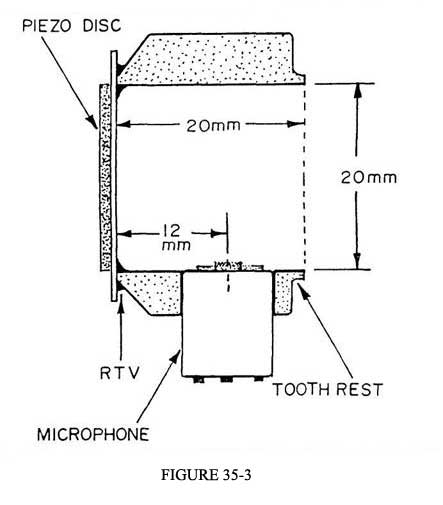
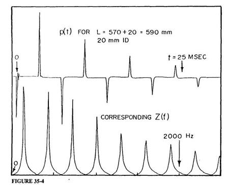
The impedance head used in our present experiments is of the sort shown in Figure 35-3 (Ibisi and Benade 1982). The primary sound source is a 27-mm diameter piezoelectric "beeper" disc bonded to the end of a short piece of 20-mm ID, 32-mm OD heavy-wall phenolic tubing by a bead of RTV rubber. The pressure signal is detected by an electret microphone whose 3-mm aperture looks into the tube only 12 mm from the face of the piezoelectric driver. If the piezoelectric transducer is considered to be a lossless single-mode harmonic oscillator, then a linearly rising ramp drive voltage will produce a single velocity pulse of the form
v(t) = V[1 - cos(2πt/T)] (35-16)
for 0 < t < T (zero otherwise), provided that the ramp duration T is exactly equal to the natural period of oscillation of the transducer. Only a slight modification of the drive voltage waveform is required to assure a very similar excitation velocity signal when account is taken of the fact that the transducer is a damped oscillator (a detailed report of these and other matters is in preparation for submission to JASA). Suffice it to say that our excitation pulse has a FWHM of about 0.083 milliseconds, so that FFT measurement of Zu is possible without correction up to well beyond the 2500-Hz limit of our present major concern.
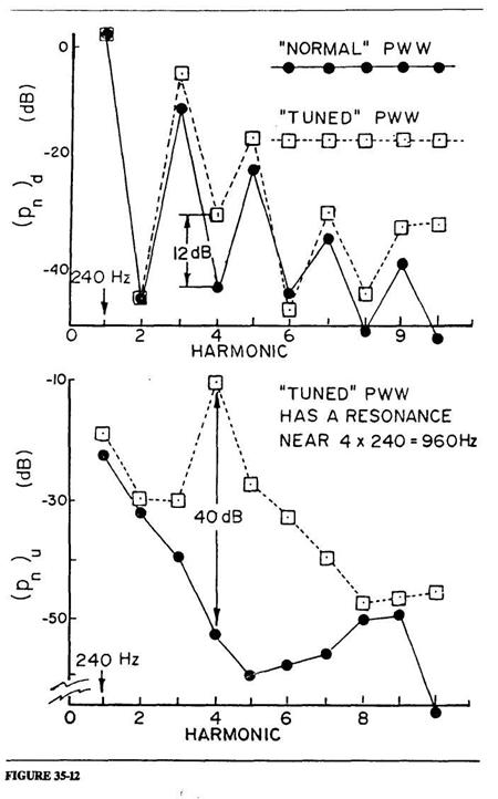 The top half of Figure 35-12 shows the sound spectrum (pn)d measured in the mouthpiece of our IAC under two experimental conditions. The lower half of the figure shows the corresponding two spectra (pn)u measured in the player's mouth. The solid lines in both graphs shows the spectra measured under the "normal" condition that no resonances in the PWW are anywhere near the resonances of the IAC. The mouthpiece spectrum under these conditions is of exactly the form that has become familiar to us in our work with woodwinds over many years. Its shape is controlled by the impedance of the IAC, as we have become accustomed to take for granted (see Equation 35-8). We recognize, now, that the relative invisibility of the PWW generally comes from the fact that its resonances do not normally lie in places that give rise to the special circumstances referred to above, but not yet elucidated. The solid line in the lower part of the figure, which shows the nature of the corresponding spectrum in the player's mouth, does not have any particular features that we need to dwell upon at the moment.
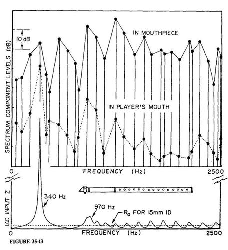 We now take our first step in describing the special circumstances under which the PWW can make its presence felt in an overt way. Consider a dynamical system in which the IAC is designed so as to give only a single strong resonance peak (an example of which is shown in the lower part of Figure 35-13, where the peak is at a frequency fa = 340 Hz). If then the reed is instructed on its downstream side by such an air column and on its upstream side by some version of the PWW, there is no harmonic collection of resonance peaks that can cooperate in setting up a well-defined regime of oscillation and its corresponding harmonic spectrum. If the player will, however, explore the possible variations in Zu(ω), it proves possible for him to find one or more cases where the tallest peak of the PWW resonance lies at such a frequency fb that energy generation at this frequency and at fa is sufficient to feed all of their intermodulation products, some of which may fall on top of one or more of the remaining (inharmonically positioned) resonance peaks of the PWW. The upper parts of Figure 35-13 show the enormously complicated mouthpiece and mouth spectra measured for such a special case, whose sound is recognizable by musicians to be of the complexly interwoven type that they are accustomed to calling a "multiphonic." Oscillatory energy is primarily produced near the frequency of the IAC impedance maximum and at one (or perhaps more) of the PWW resonance peaks. Because of the strong nonlinearity of the reed valve, these two or three primary spectral components have bred a whole host of intermodulation products. We have produced numerous versions of the IAC and PWW configuration described here, and are always able to produce multiphonics in exactly the same way. In all cases it has been possible to analyze the spectra in the manner already worked out for the analogous type of oscillation produced by an IAC whose resonances are inharmonic (Benade 1976, chap. 25).